Bert — The Autonomous Hovercraft
Designed and built an autonomous hovercraft using nonlinear control, digital twin simulation, and onboard sensing. Bert won the class-wide competition in BU’s Motion Planning course and was later featured at the RASTIC inauguration.
Boston University – ME461: Motion Planning
Co-developed with George Knight under Prof. Roberto Tron.
Our hovercraft, affectionately named Bert (Alberto), won the class-wide competition among 40+ autonomous vehicles and was later showcased at BU’s RASTIC (Robotics & Autonomous Systems Teaching Innovation Center) inauguration.
This is a project stub. I need to find more pictures from the project to update.
Overview
Bert is an autonomous hovercraft designed and built from scratch as part of the graduate-level course ME461: Motion Planning at Boston University.
The project integrated nonlinear control, path planning, and state estimation into a fully functional system capable of following waypoints and adapting to sensor feedback.
Key Highlights
- Objective: Develop an autonomous hovercraft for motion planning and control competition
- Hardware: Dual-thrust, dual-vane hovercraft with onboard LiDAR and IMU
- Controls: Nonlinear control system using Jacobian-based state feedback
- Planner: Quadratic potential field path planner in 6D state space
- Sensing: Accelerometer and LiDAR-based localization with rolling-shutter correction
- Result: First place in the class competition; showcased at BU’s RASTIC event
Design and Operation
Bert’s behavior follows the classic OODA Loop (Observe → Orient → Decide → Act), adapted from aviation decision theory to robotics.
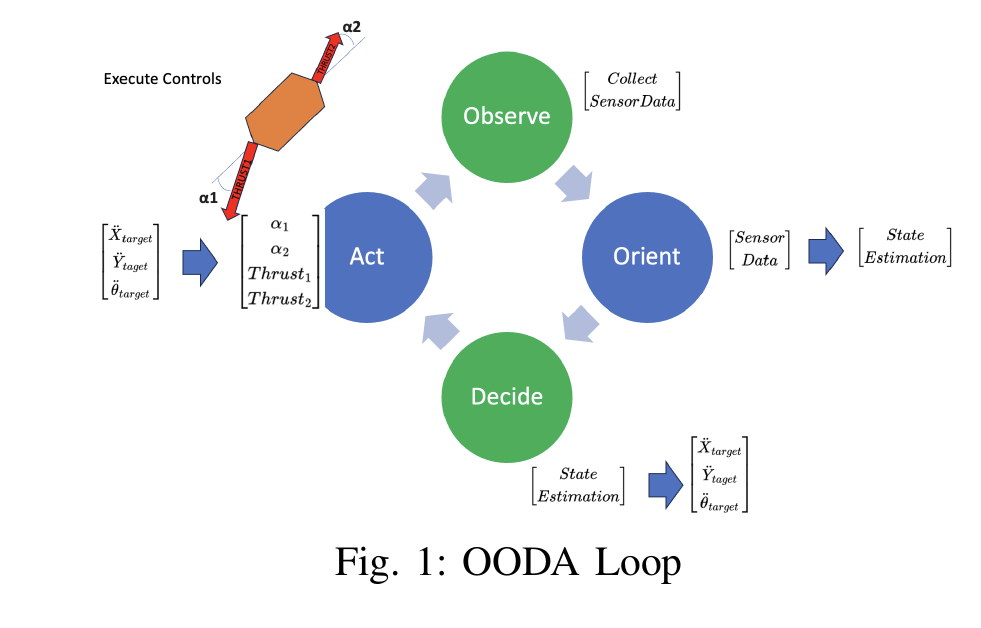 Observe–Orient–Decide–Act loop implemented as Bert’s high-level control architecture
The hovercraft’s challenge was underactuation — four control inputs (two thrusts, two vane angles) but only three degrees of freedom.
This required solving a nonlinear, underdetermined system of equations in real time.
Sensing and Localization
Bert’s navigation relied on a combination of LiDAR and IMU data.
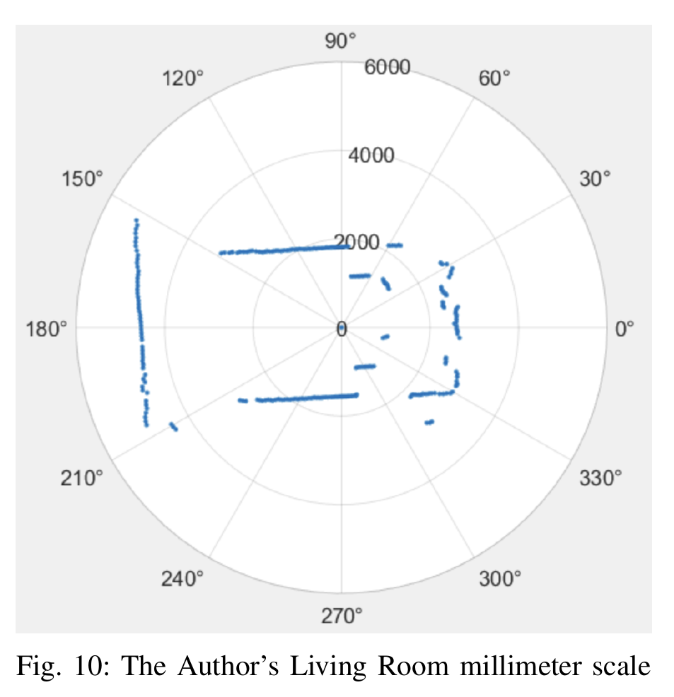

LiDAR readings were used to calculate heading and lateral displacement, while accelerometer data provided forward velocity estimates.
To compensate for rolling-shutter LiDAR delay, Bert used gradient descent on successive LiDAR frames to minimize position error and maintain real-time state estimates.
Path Planning and Control
Path planning was implemented through a quadratic potential field planner in a six-dimensional state space
$$ ((x, y, \theta, \dot{x}, \dot{y}, \dot{\theta})).
The planner’s goal was to minimize both positional error and energy expenditure, balancing efficiency and stability.
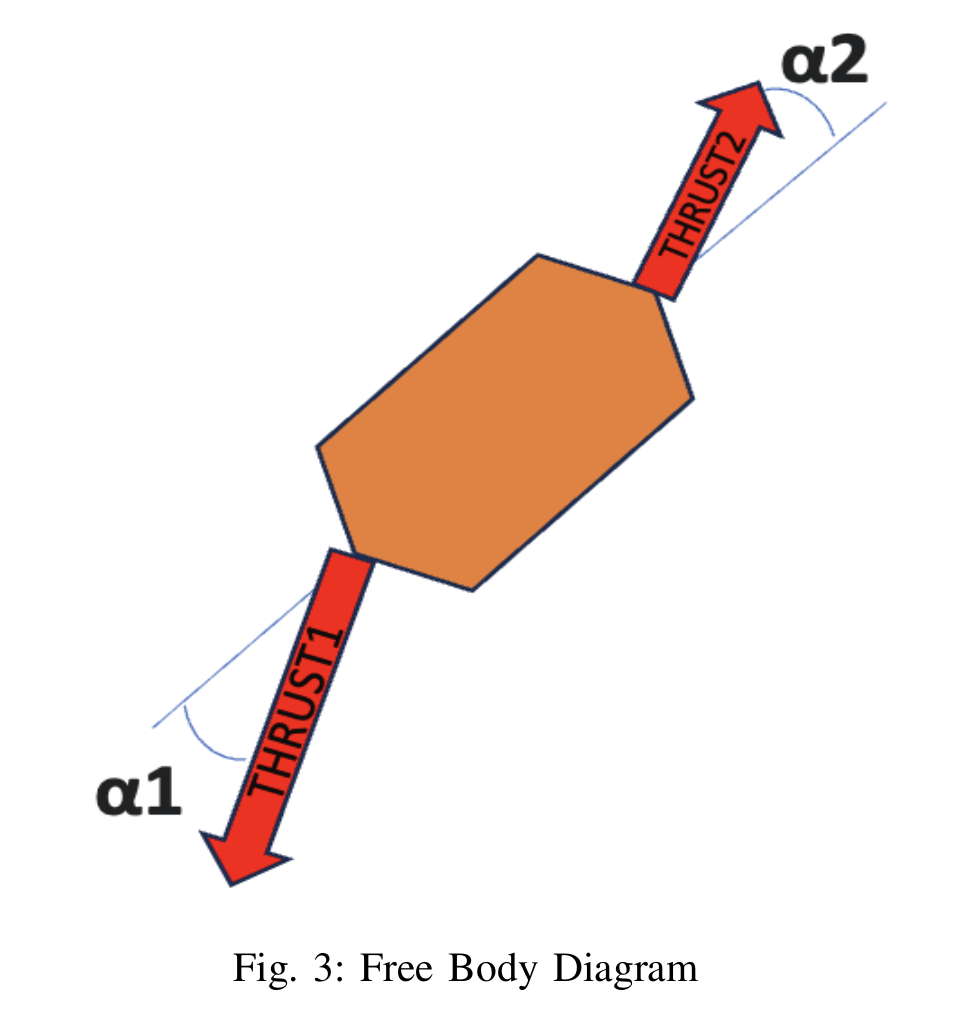 Free-body diagram of Bert showing dual-fan thrust and control vane configuration
The system originally solved for control inputs using gradient descent, but was later reformulated using the Jacobian matrix with an added energy-efficiency constraint as a fourth equation, producing a stable, well-conditioned solution.
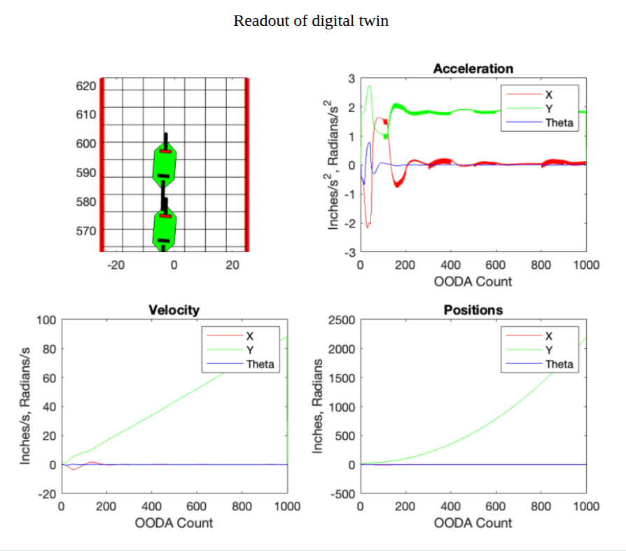
Simulation and Digital Twin
MATLAB-based digital twin used for closed-loop simulation and controls validation
A detailed digital twin of Bert was built in MATLAB/Simulink to test controllers before deploying them to hardware.
This virtual model simulated thrust, drag, noise, and LiDAR inputs, allowing rapid iteration on the control architecture.
Hardware and Integration
The physical hovercraft included:
- Raspberry Pi 4B (central control and computation)
- Two brushless DC fans with independent servo-controlled vanes
- RPLiDAR 2D 360° scanner
- MPU-6050 IMU sensor
- Custom 3D-printed mounts and skirt system
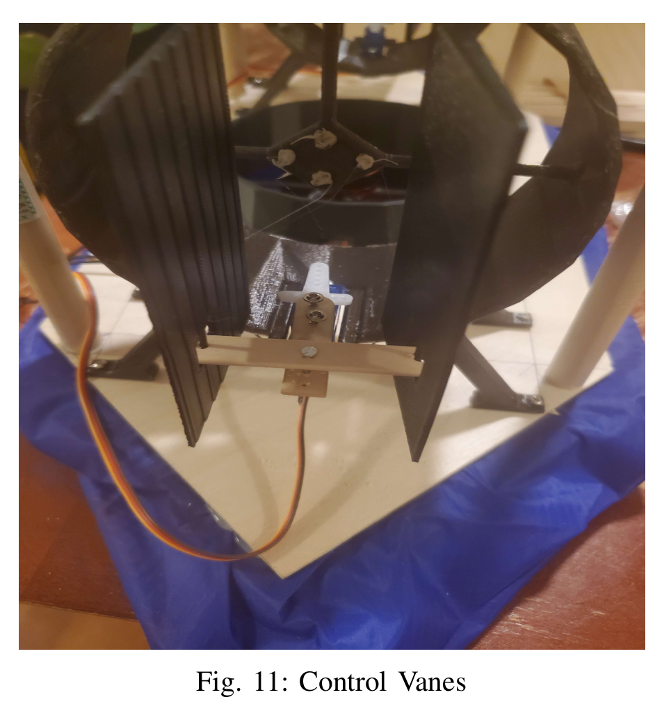 Control vane assembly providing independent yaw and translation control
 Hardware-in-the-loop test of an early Bert prototype running simulated trajectory tracking
Results and Testing
Bert’s control framework successfully allowed stable navigation through simulated and physical corridors, reaching all waypoints without wall collisions.
The control strategy proved robust against noise and underactuation.
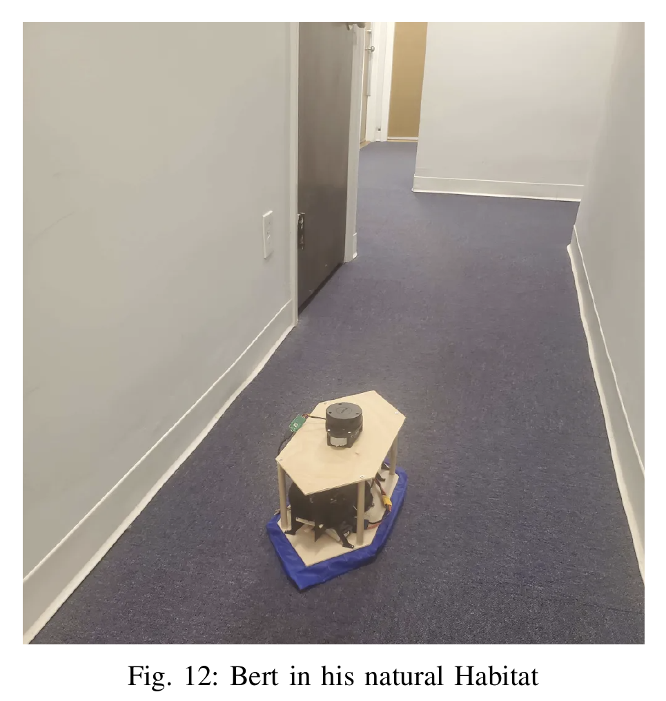 Bert in his “natural habitat” — a hallway
Bert’s system achieved the highest performance score among over 40 submissions and was later featured during the BU RASTIC inauguration, representing student-led innovation in autonomous systems.
Lessons Learned
- Real-time optimization bridges the gap between theory and hardware.
- Digital twins accelerate testing and minimize hardware risk.
- LiDAR-IMU fusion with rolling-shutter correction significantly improves localization.
- Physical tuning and control parameterization require iterative validation.
Gallery
| |
| Control hierarchy (OODA) | LiDAR scan used for orientation and localization |
| |
| Servo-driven vane assembly | MATLAB digital twin simulation |
| 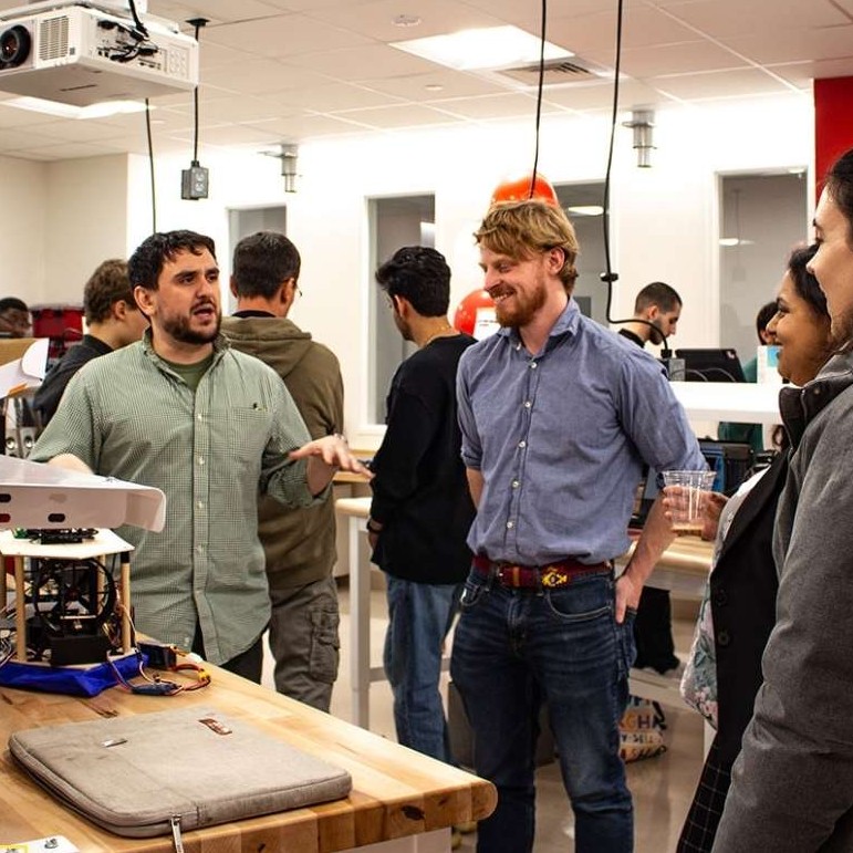 |
| Bert in final testing environment | Team photo post-competition (Mitch and George, center) |