Chess-Playing Robot — Basic Electronics
First electronics shakedown! Getting basic CNC functionality up and running.
Work in Progress — Basic Electronics
Developing the electronics needed for basic motion. Advanced path planning and algorithmic control and sensors coming eventually.
Last post’s TO-DO list COMPLETE!
- Printed new carriage parts
- Mounted linear rails and bearings
- Integrated stepper driver and GRBL test
- Wired endstop sensors
- Begin motion testing
And most importantly
IT MOVES AND HAS GOOGLY EYES
Research
Early in my research for this project I came across GRBL, and the CNC Shield for the Arduino Uno. They are the standard answer for hobbyists trying to make their own custom CNC machines, plotters, and some 3D printers. Which is kind of what this robot is designed to be. It’s got about 64 specific locations where we can send the end effector to pick and place. Its kinda like a tool change at 64 locations. GRBL is flashed onto the Arduino, and Gcode can then be sent to the robot directing its movements.
Gcode is the industry standard for this type of motion. CNCs and 3D printers all use it. (This version of GRBL is slightly modified to accept servo commands.)
Arduino and Motor controller
My solution to use this pair and is obviously financially motivated. Once I get everything up and running the way I like, I can look into more powerful controllers if needed… But honestly for this application all the controller needs to do is wait for the Gcode to come from our pipeline and make a few efficient movements.
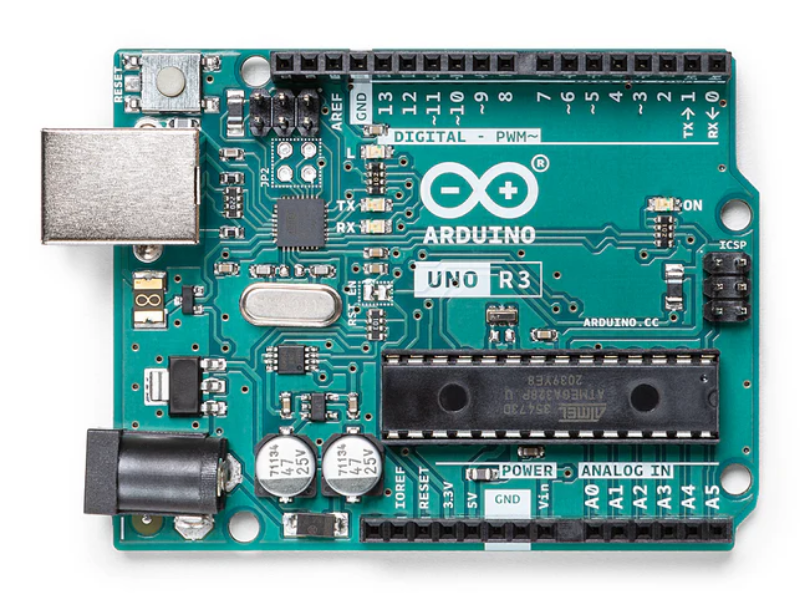
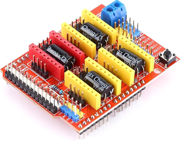
 The shield literally just pops in on top of the Arduino and is done. A few enabling jumpers and it will run on its own power supply that we give separate to the Arduino drawing its 5 volts from the USB.
On top of THAT the shield takes a few dedicated motor drivers. One for each stepper motor we are running.
All told the electrical hardware was pretty cheap:
- Stepper Motors $16.99 (x3 I got an extra)
- Arduino Uno Kit $26.99
- CNC Shield
- Arduino Uno
- 4x Motor Drivers w/ radiators
- 4x end stop switches
About $78 plus tax.
Universal Gcode Sender
 Of the multitude of different methods for interfacing with the Arduino, it’s the most straight forward I’ve found so far. It has the most features and customization options to use until I build my own python and ROS2 pipeline. It can import images and convert them to Gcode, which is the next step on the road. It lets us send test commands in order to get everything dialed in and make sure the structure can stand up to the movement in terms of things like rigidity and vibration.
End Stops
I ended up using 4 switches for end stops for maximum safety. The two on the ‘-‘ side, (towards home) are important for homing the system each time for calibration purposes. The two at the extremes of the envelope are mostly useless since I will be including soft limits for the robots travel, but they will be useful in case of coding errors or swapped symbols… not that I would ever make such a mistake.
The switches themselves are just hot glued in place at the extremes of the Y-Axis and on the bottom of the X-Carriage as it moves from end to end.
Goals for next time!
I know this post is pretty quick. I’ll post more next time, working out the electronics was more work than anticipated.
- Design and Prototype Plotter head
- Integrate to run on Raspberry Pi
- Draw something cool!
- Re-design and print permanent mountings for end stop switches
- Maybe add a joystick and arcade buttons?!?