Chess-Playing Robot — Assembly & Prototyping
Mechanical redesign and assembly of robot parts for the autonomous chessboard project. REAL HARDWARE!
I’ve been busy applying for jobs and working on some other projects, but here’s an update on the Chess Robot. Seems like things are getting a little busy! May not get to do these updates as often as I would like!
Work in Progress — Assembly and Prototyping Stage
This post focuses on the assembly of the first prototype parts for the chess robot.
Design Goals
The goal for this iteration was to:
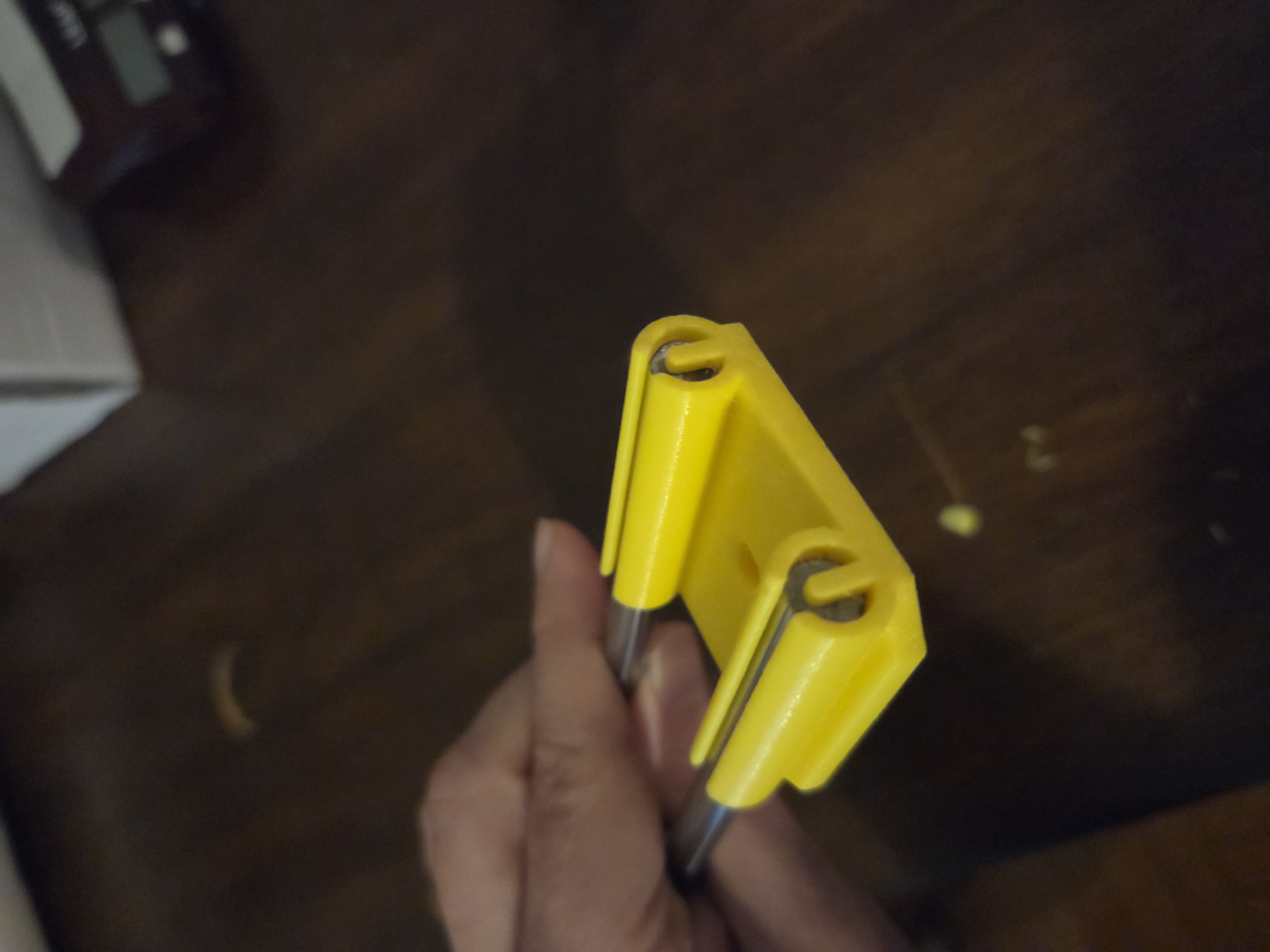
- Put the pieces we printed on the smooth rails and bearings to test fit and function
- Determine any missing design elements
- Redesigning printable components
- Validate assembly tolerances and motion clearances
Smooth Rail System
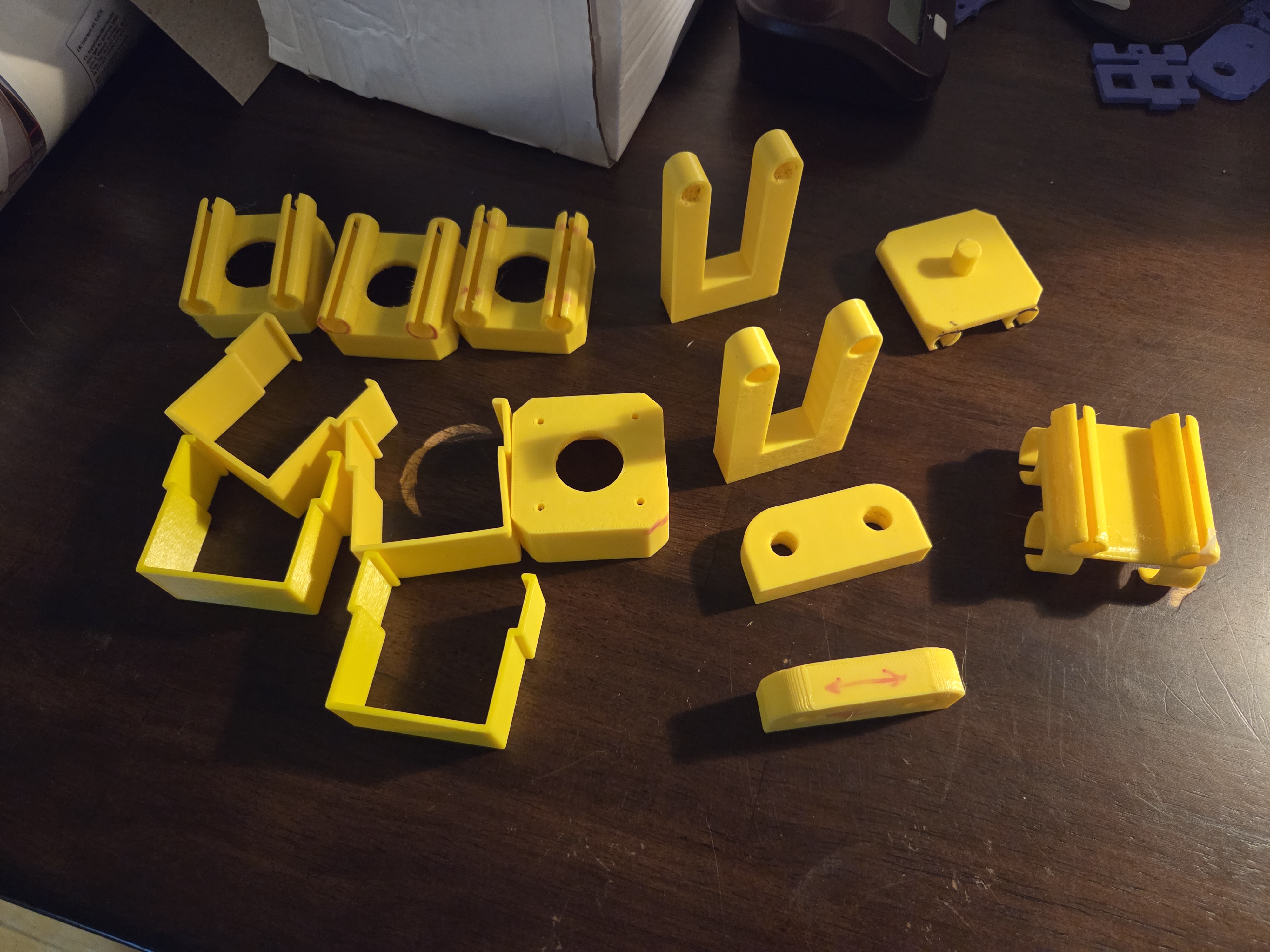
Below are some pictures of the iterations of different components. I have a habit of writing on printed parts in marker where changes need to be made. This helps me visualize the changes and makes sure I don’t accidentally install the wrong version of a part. Sorry if some of my “notes” sneak through in the pictures.
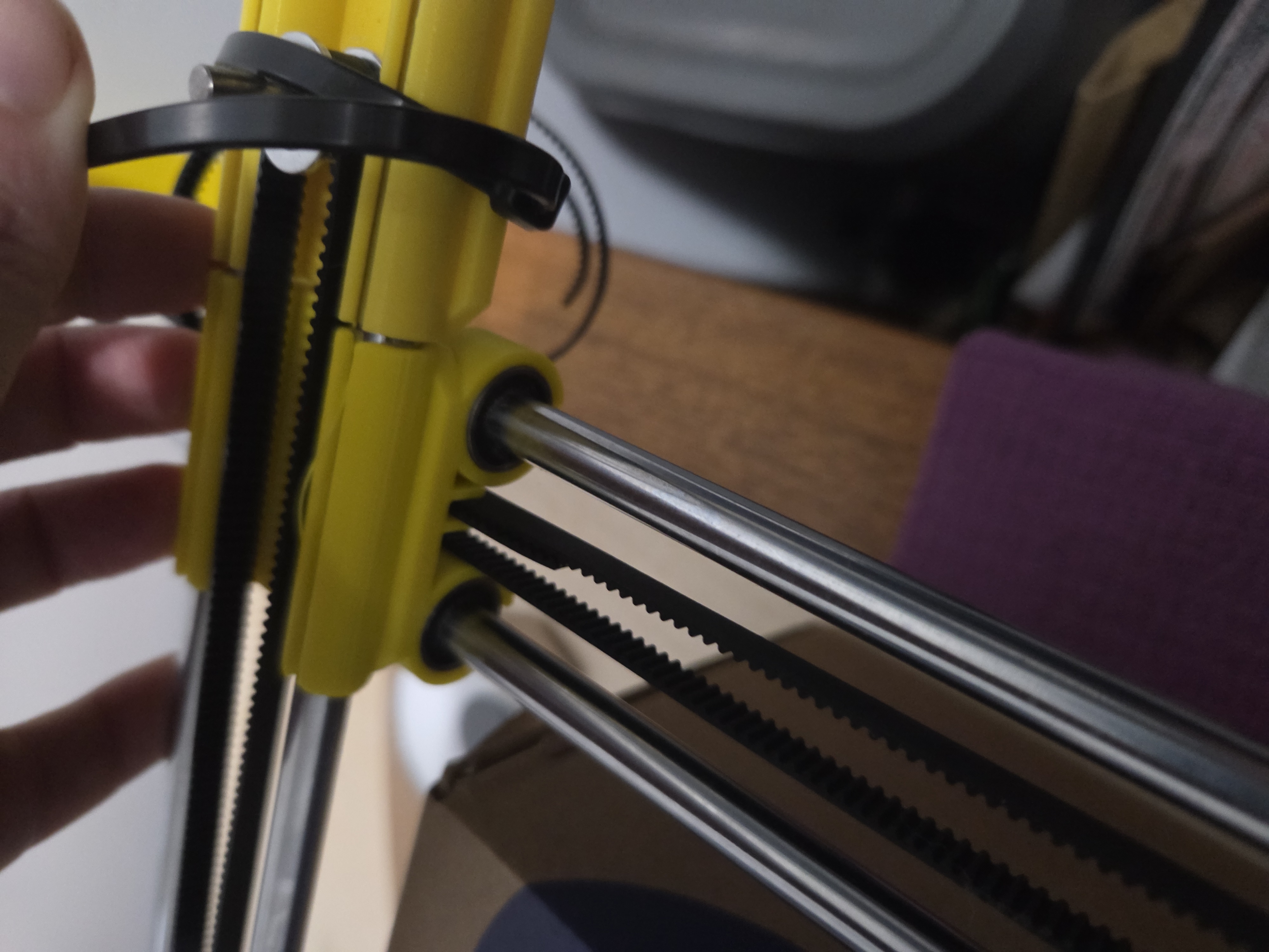
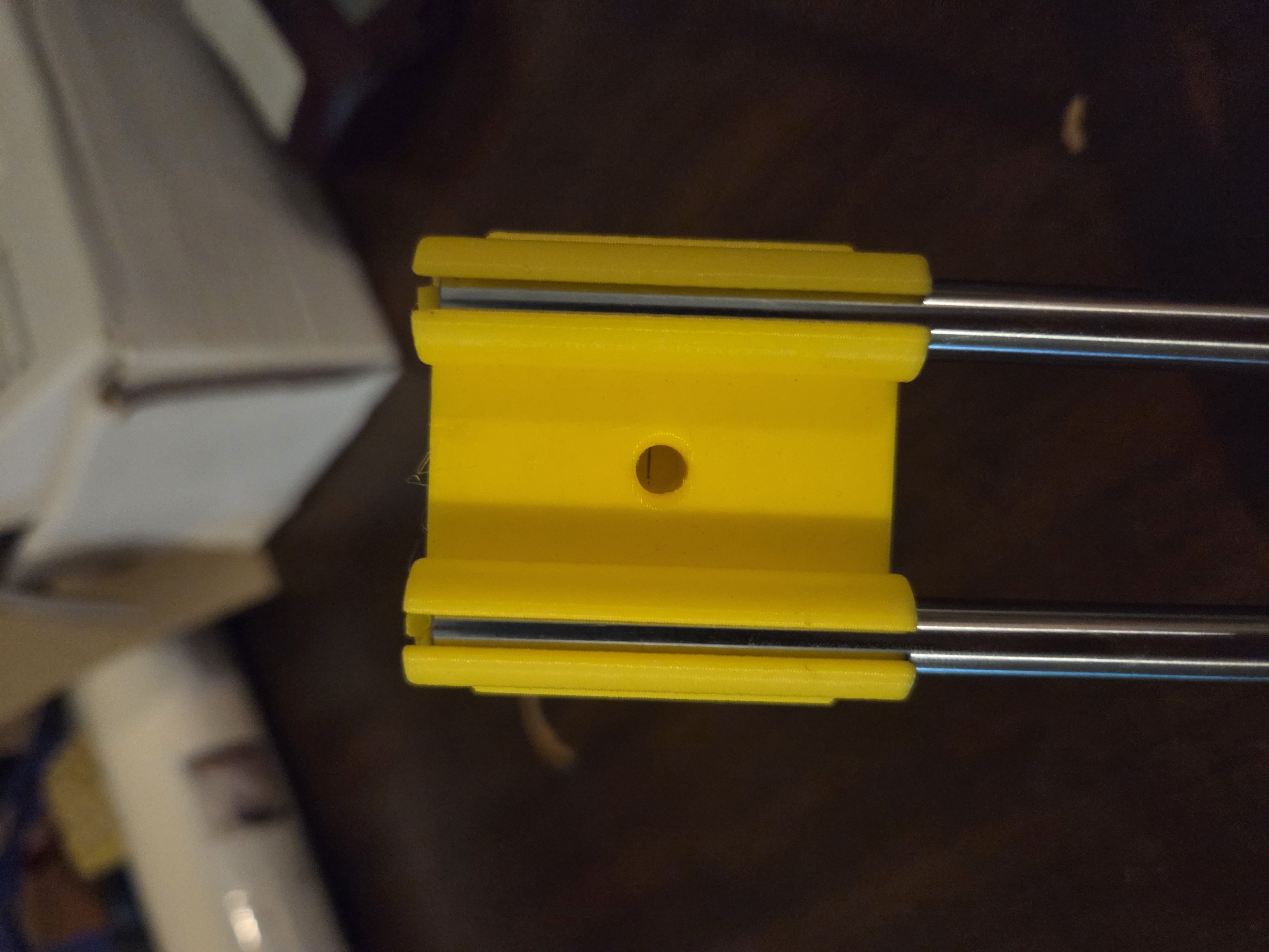
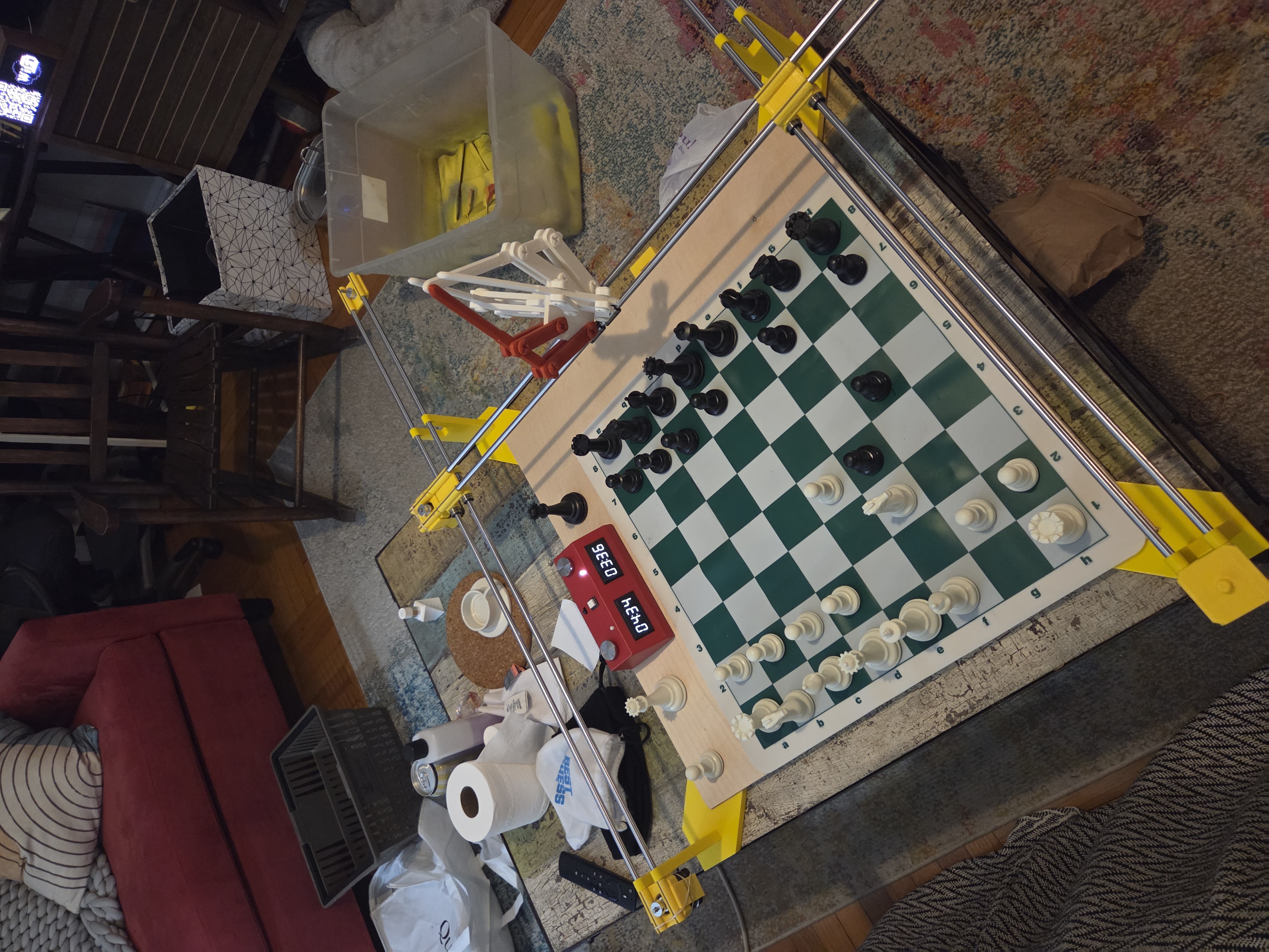
I settled on an 8 mm rail system. Specifically 4 for the Y-axis (2 on each edge) and 2 on the X-axis. The pairs of rails provides stability, which we will need for the end effector riding on the X-axis carriage. The mounting holes in the stepper motors, and therefore the smooth rail attachment fixtures that sit over the mounting screws, are 31 ± 0.2mm apart. Many of my design details are flowing from the constraints of the hardware, for now. If stability becomes an issue we can redesign and make them further apart.
Major Components Assembled
- Linear rail system
- Motor Mount
- Idler Mount
- Y-Axis Carriage
- End effector Carriage
- Rail Supports and Alignment Brackets
Gantry and Motion Envelope
 I wasn’t able to track down my video of this step (and to give you a peek behind the curtain, I have made significant progress since then), so enjoy this gif of the 3D model.
Prototype Parts
Some changes to the parts were required.
- It became clear that the motor mount screw holes were inaccessible so I widened the clearance for a screwdriver.
- The tolerance of printed parts was difficult to dial in. It depended on the orientation of the part being printed. I added a flex slot, which may come back to bite me if the gantry lacks rigidity.
Current Status
- Printed new carriage parts
- Mounted linear rails and bearings
- Integrated stepper driver and GRBL test
- Wired endstop sensors
- Begin motion testing
LET’S MAKE SOMETHING MOVE
Here’s a sneak peek of what I’ve been working on for the next post.