Chess-Playing Robot — Concept & Design
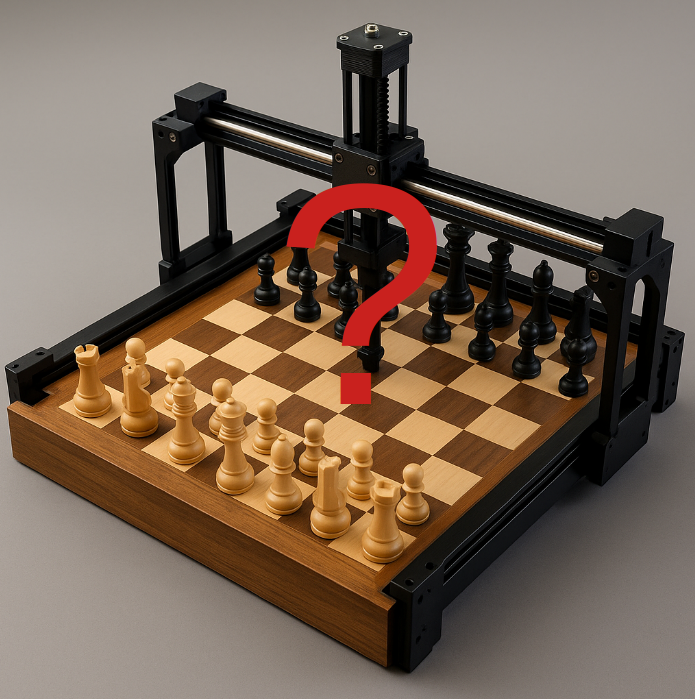
Concept for a fully automated chessboard that can detect and move pieces using an XY gantry and sensors. The project combines mechanical design, embedded control, and maybe a bit of AI for game logic.
Work in Progress — Concept Stage
A personal robotics build exploring automation, sensing, and mechanical precision through a classic game: chess.
The Idea
I’ve always loved projects that sit at the intersection of mechanical design, control systems, and playful interaction.
And I love chess. But I’m not very good.
The goal here is to build a fully autonomous chessboard that can detect where every piece is and move them using an XY gantry, much like a compact CNC machine.
 And win games against my friends that I can’t beat. For a full and comprehensive look at all the friends I can’t beat, check out Prospect Park Chess Club, another of my projects.
![]() Pieces will be embedded with RFID tags or small magnets, and the board will use reed switches or Hall sensors arranged in an 8×8 grid to detect their presence.
Pieces will be embedded with RFID tags or small magnets, and the board will use reed switches or Hall sensors arranged in an 8×8 grid to detect their presence.
The robot will handle everything from opening moves to checkmates — while the human opponent watches the system beat them. Probably with Stockfish.
Project Goals
- Detect all 64 board positions automatically
- Move pieces precisely using a 2-axis gantry and gripper
- Integrate computer vision or engine-based move logic later
- Learn about sensor multiplexing, embedded control, and motion planning
- Keep the aesthetic of a normal chessboard — not a lab bench robot
- AS MANY GOOGLY EYES AS POSSIBLE
Design Overview
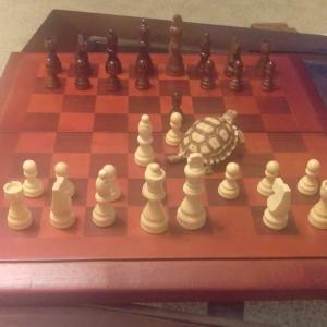 Since I was forced to abandon my attempts to train a tortoise to play chess and my cats are not interested, I will have to build a robot instead.
The robot will use a CNC-style XY gantry with an end effector that slides over the board surface. Each square will be equipped with some kind of sensor, wired in a matrix or multiplexed configuration to minimize pin count. Currently investigating the pros and cons of reed switches RFID tags and Hall effect sensors. I may also revisit my chess computer vision algorithm, but we’ll call that a stretch goal (as is the post about it).
Sensor Comparison: Reed vs. RFID vs. Hall Effect
| Feature | Reed Switches | Hall Effect Sensors | RFID Sensors |
|---|---|---|---|
| Detection Type | Mechanical magnetic switch (open/close) | Solid-state magnetic field detector | Passive tag + active reader antenna |
| Output | Digital (binary on/off) | Digital or analog (field strength & polarity) | Digital ID from tag |
| Cost | Very low (~$0.05–$0.20 each) | Low-moderate (~$0.30–$0.80 each) | High (reader + tag per square) |
| Wiring Complexity | Simple matrix scanning | Requires power & signal lines | Complex (multiple readers or multiplexing) |
| Power Consumption | None (passive) | Continuous draw (3.3–5 V) | Moderate (RF field generation) |
| Durability / Lifespan | Mechanical wear over time (≈10⁶–10⁷ cycles) | Essentially infinite (no moving parts) | Excellent (no contact) |
| Response Speed | Slow-moderate (1–2 ms) | Very fast (µs) | Moderate (10–100 ms) |
| Polarity Sensitivity | None (any magnetic pole triggers) | Can detect polarity and magnitude | Not magnetic-based |
| Noise / Interference | Immune to EMI | Can pick up magnetic noise | Susceptible to RF coupling/interference |
| Ease of Integration | Easiest (GPIO grid or mux) | Moderate (requires calibration & power rails) | Difficult (protocol handling, antenna tuning) |
| Unique Identification | No (only position detected) | No (but analog value possible) | Yes (unique ID per tag) |
| Best Use Case | Simple piece detection, early prototype boards | High-speed sensing or polarity-encoded pieces | Distinguishing specific pieces or research demos |
| Main Drawback | Fragile glass capsule, binary only | Needs continuous power, sensitive alignment | Cost and wiring scale poorly |
🧠 Summary
- Reed switches: ideal for first prototypes — simple, cheap, and reliable enough for static piece detection.
- Hall sensors: excellent upgrade path — durable, precise, and polarity-aware once power distribution is in place.
- RFID: powerful for unique piece identification, but wiring, power, and cost make it best for advanced versions.
At this stage I’m prototyping the grid using Raspberry Pi Pico microcontrollers, each handling one section of the board and communicating position data to a Raspberry Pi 5 over serial or I²C.
The plan is to modularize it so that we can test the various different sensors. My bet right now is on the Hall sensors.
Inspiration
Commercial products like DGT Boards have proven the concept, but I want something open-source: a platform that’s not only fun but also extensible for research in localization, path planning, and human-robot interaction.
The mechanical side — building a precise but affordable gantry — is just as interesting as the software. I’m borrowing techniques from CNC design, 3D printer kinematics, and my experience with motion planning to make the movement smooth and deterministic.
I also run one of the largest chess clubs in Brooklyn as mentioned above, and it would be cool to be the only club with a chess robot.
Current Status
Right now, the focus is on:
- Testing sensor arrays and multiplexing options
- Build Bill of Materials (BOM) for tests
- Order Parts
- Assemble and test
- Validating sensor strength and detection distance
- RFID
- Hall effect
- Reed switch
- Planning the mechanical envelope for the gantry and frame
- Modeling the board layout in CAD
Next Steps
- Build a 3×3 (maybe bigger?) test section with real sensors
- Design modular PCBs for sensor arrays
- Prototype end effector with electromagnet and Z-axis lift
- Maybe start with a CNC plotter design?
- Integrate with chess engine (Stockfish) for full automation
- Explore ROS2 interface for motion planning and visualization
Future posts will go into the details — electronics, wiring diagrams, PCB layout, and control firmware.