Chess-Playing Robot — CAD & Prototyping
Early CAD models and mechanical design exploration for the autonomous chessboard project. Building out the frame, end effector, and first printed parts.
Work in Progress — CAD & Prototype Stage After finalizing the core concept, the next step was turning ideas into geometry. This post focuses on the mechanical design and first prototype parts for the chess robot.
Design Goals
The goal for this iteration was to:
- Translate the concept sketches into parametric CAD models
- Define the mechanical envelope for the chessboard, rails, and Z-axis
- Start designing printable components
- Validate assembly tolerances and motion clearances in simulation
Onshape CAD Development
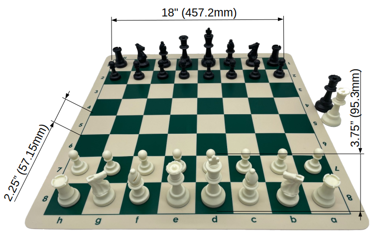 Overview of the dimensions of a standard chessboard
All design work is being done in Onshape, which makes modeling and versioning easy between mechanical and electronics subsystems.
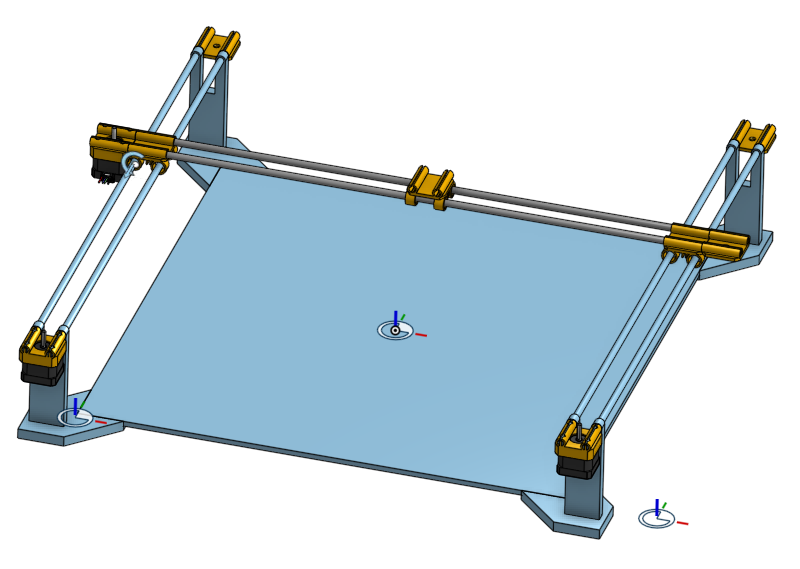
The first assemblies focused on the gantry geometry — ensuring travel range covers all 64 squares while keeping the frame compact… If maybe not as compact as the cool render from last post.
The goal is to use a normal tournament sized chess board. Its easily recognizable by all chess players, and I have about 50 of them laying around… Just in case I mess up really badly. On this sized board the squares are 2.25 inches, but we’ll call it 57.15 mm since we aren’t monsters. And the king height is just under 4 inches (3.75” 95.3 mm) so we’ll give ourselves a vertical envelope of 5 inches to work with for clearance.
All that said it would be cool if the board also used a normal chess clock. So, we add an extra 3 inches for that, and with the boarders of the board we have about a 2 foot square to work with.
Major Components Modeled
- Linear rail system for X and Y motion
- Motor Mount holding the stepper motors in place
- Idler Mount providing a pivot point for the belt dirve
- Y-Axis Carriage a Carriage to slide up and down the Y-axis that the X-axis will ride on
- End effector Carriage designed to hold a small electromagnet or gripper
- Rail Supports and Alignment Brackets to hold the rails high enough off the playing surface and to connect them to the wooden board surface
Gantry and Motion Envelope
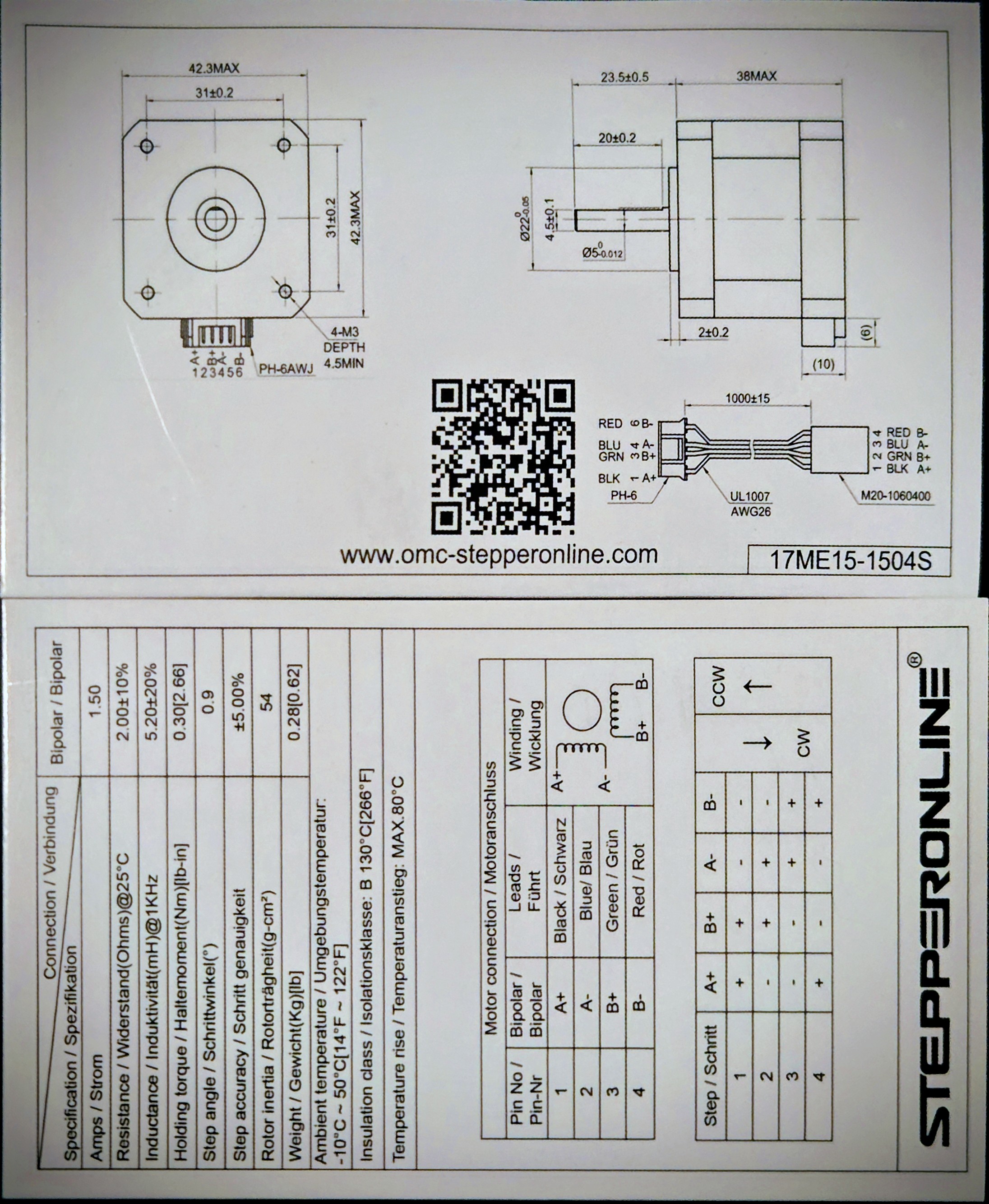
The separation for the linear rails was determined by the mounting holes in a standard Nema 45 stepper motor. Which thankfully has a great data sheet.
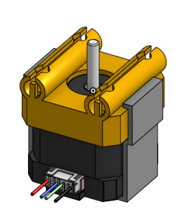
and its modular mount
While the first version uses a basic Cartesian XY motion with 2 (with the option for 3) stepper motors driving belts. The design leaves room for experimenting with CoreXY or H-bot motion later — useful if higher speeds or a cleaner wiring path become necessary.
Prototype Parts
The first prototype components are being printed on a Prusa MK3 using PLA for stiffness.
The focus was on validating:
- Fit between rail blocks and carriage plates
- Belt tensioning geometry on the 8mm smooth rods
- Endstop and sensor mounting points
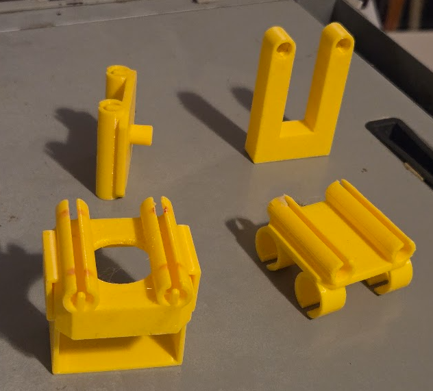 First batch of printed parts — carriage and motor mounts, pully idler, and frame brackets test half
Next Steps
- Refine the CAD model and finalize frame dimensions
- Design and Print an end effector. Since Chess is pretty far off without additional electronics we will make a plotter first.
- Begin PCB layout for sensor grid modules
- Start wiring prototype electronics for manual motion testing (GRBL / Arduino)
- Capture motion footage for the next post